Sizing an air source heat pump for the real building, not the rule of thumb
Most underperforming heat pump installations in the UK were decided in the first hour of design, long before a single unit arrived on site.
The rule of thumb is the problem
The habit of sizing by floor area — so many watts per square metre — comes from an era of oversized gas boilers, where excess capacity cost little more than a slightly larger flue. A heat pump behaves differently. It is a modulating machine with a minimum output, and when that minimum sits above the building's actual demand for most of the heating season, the unit short-cycles.
We build a room-by-room heat loss model to MCS and BS EN 12831 principles, using measured fabric build-ups, real air-change rates and verified window specifications. On a recent 680 m² residence that exercise returned a design load roughly 30% below the figure a floor-area estimate would have produced.
Design flow temperature is the real lever
A heat pump's coefficient of performance falls as flow temperature rises. Every degree matters. Designing a system around 35°C flow instead of 50°C typically lifts seasonal performance by a fifth or more, which shows up directly on the client's running costs.
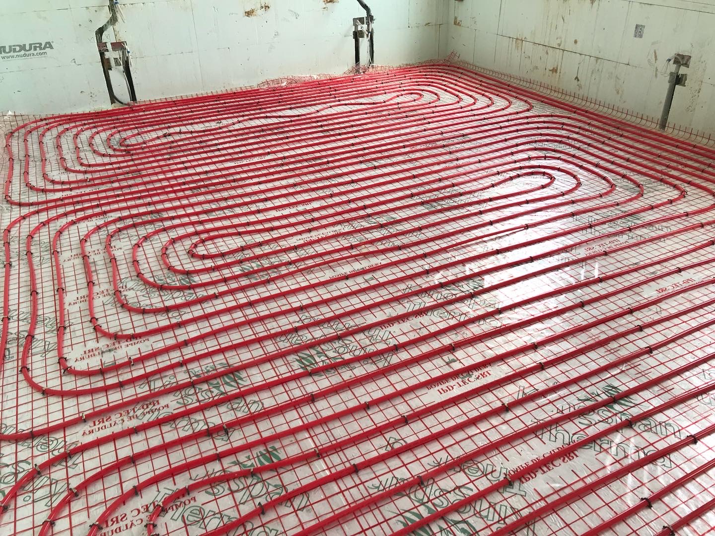
That is an emitter question, not a heat pump question. Underfloor heating at generous pipe centres, correctly sized fan coils, or oversized low-temperature radiators all make low flow temperatures achievable without compromising comfort.
Hot water, buffering and defrost
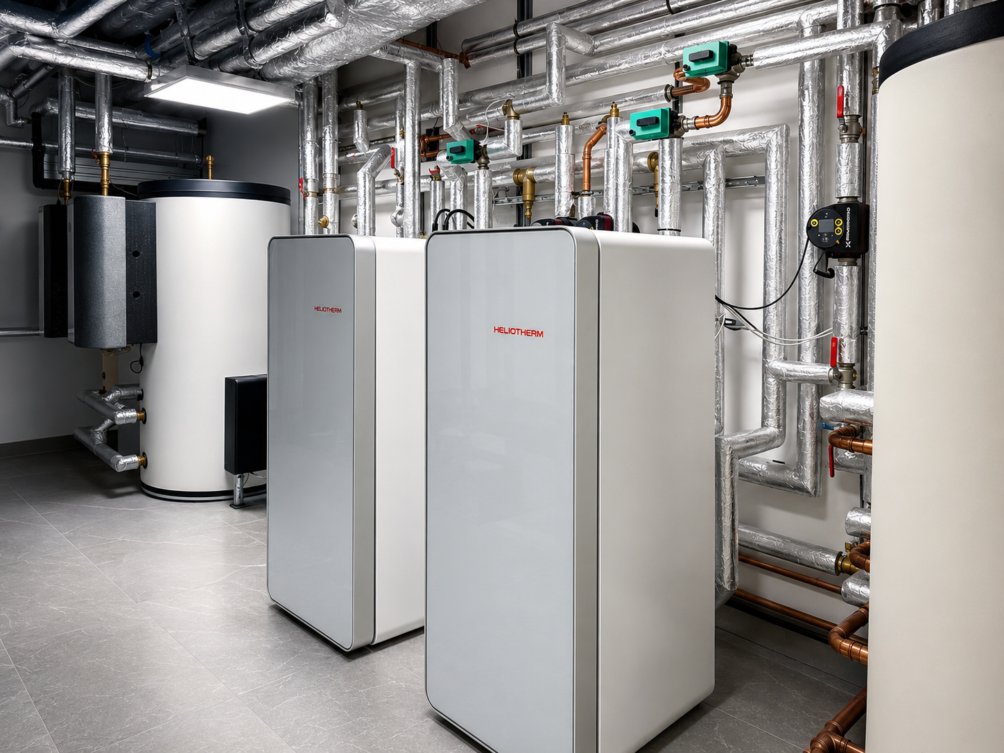
Domestic hot water usually sets the peak demand in a luxury residence, not space heating. Multiple rainfall showers running together will empty an undersized cylinder in minutes, and reheat recovery has to be designed against real occupancy patterns, not a nominal family of four.
Buffer volume needs to be sized for the defrost cycle and for minimum run time — enough to stop cycling, not so much that the system carries dead thermal mass around all winter.
What we hand over
Every Solux installation is issued with the heat loss model, the emitter schedule, the commissioning record and the measured flow rates at each circuit. If a system ever underperforms, that documentation is what makes the cause findable rather than a matter of opinion.
Planning a system where these details matter?
Send us drawings or an outline brief and we will respond with a considered mechanical strategy for your project.
Start an enquiry →